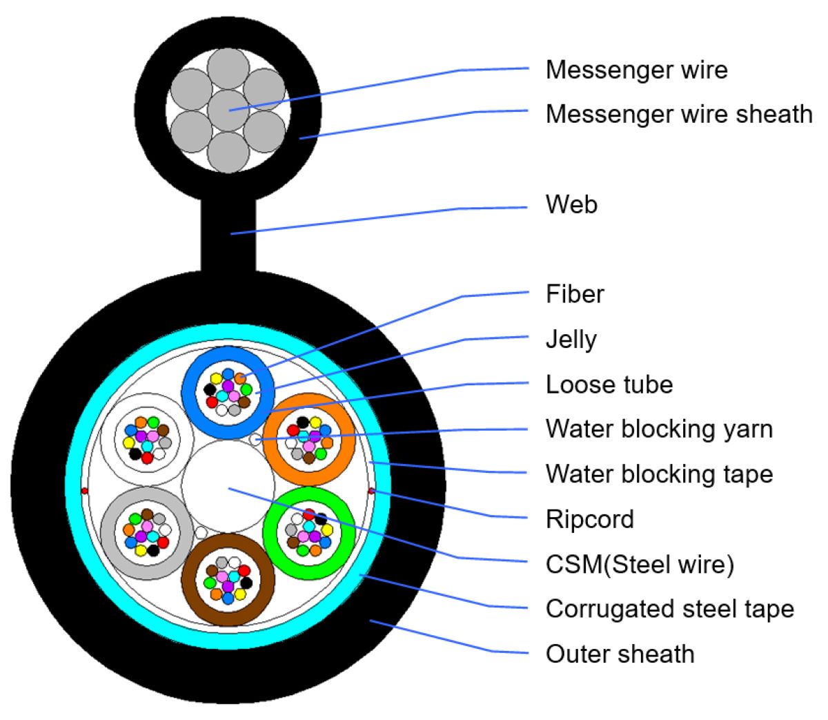
Loose tube stranded armored figure 8 self-supporting aerial cable (GYTC8S) Wasin Fujikura
Description
The fibers, are positioned in a loose tube made of a high modulus plastic. The interstice inside and outside of the tubes are filled with a water-resistant filling compound. A steel wire, coated with polyethylene if necessary locates in the center of core as a strength member. Tubers (and fillers) are stranded around the strength member to form a compact and circular cable core. The plastic coated steel tape is wrapped over the core and extruded into a polyethylene sheath to form a cable. The galvanized steel stranding wires is applied as the messenger. Finally, the messenger and the cable is linked together to form type figure -8 cable..
Feature
All section water blocking provides reliable performance of moisture-proof and water block.
Special filling gel filled loose tube provide perfect optical fiber protection.
Longitudinal corrugated steel tape gives desirable crush resistance.
Figure 8 self-supporting structure presents high tensile strength and enables easy and cost saving aerial installation.
Strict craft and raw material control enable lifespan over 30 years.
Performance
Application:Long haul and building network communication
Installation:Self-supporting aerial
Operating Temperature:-40~+70℃
Steel Messenger:1.2×7、1.5×7
Bending Radius:Static 10×D/Dynamic 20×D
Structure and technical specifications
|
Fiber Count |
Nominal Diameter |
Nominal Weight |
Max Fibers Per Tube |
No. of (Tubes + Fillers) |
Allowable Tensile Load(N) |
Allowable Crush Resistance(N/10cm) |
|
2~30 |
10.0×18.0 |
220 |
6 |
5 |
7000/4000 |
1000/300 |
|
32~36 |
10.7×18.7 |
244 |
6 |
6 |
7000/4000 |
1000/300 |
|
38~60 |
11.4×19.4 |
253 |
12 |
5 |
7000/4000 |
1000/300 |
|
62~72 |
12.0×20.0 |
280 |
12 |
6 |
7000/4000 |
1000/300 |
|
>72 |
Available upon customer’s request |
|||||


